
Technical Information
Design of Wire Mesh Mist Eliminator
Design Flow
We propose the best Wire Mesh Mist Elimiator for your operating conditions.
Design Flow
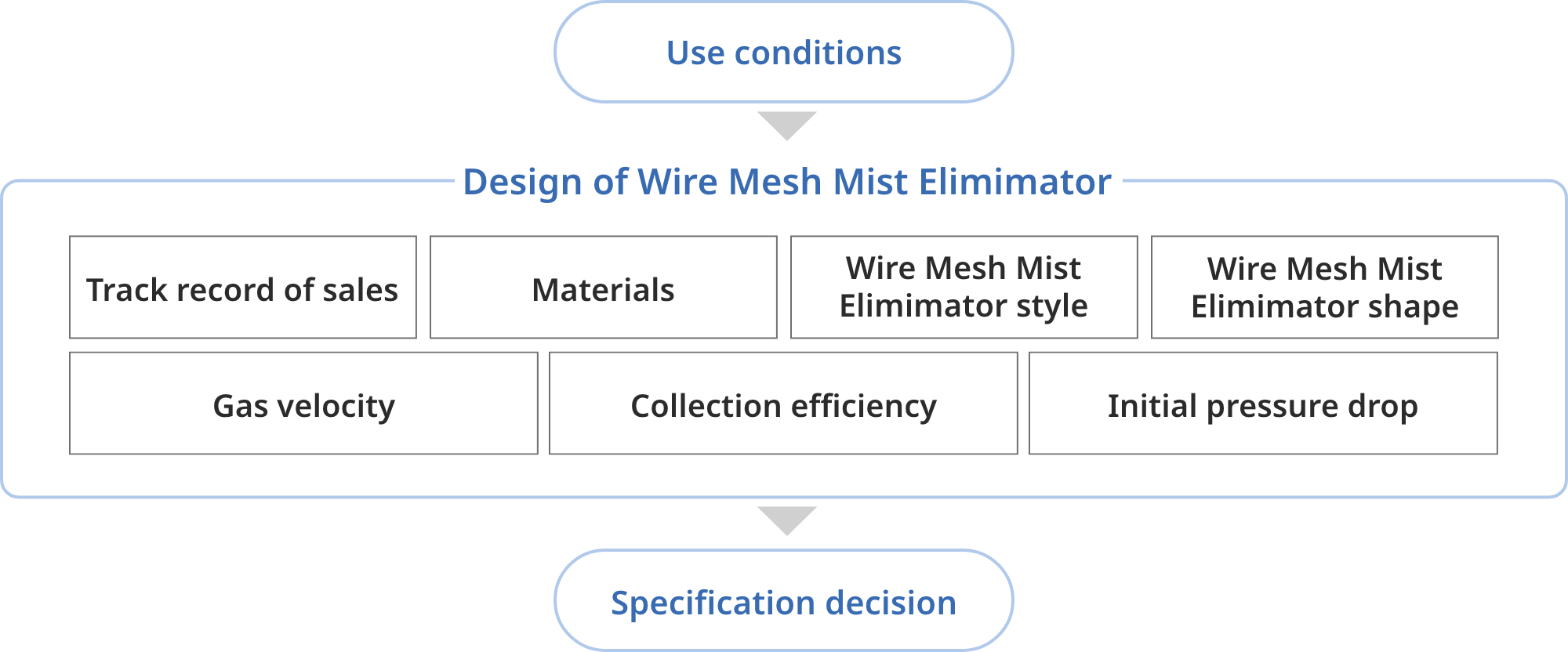
| Operating Conditions | We will check the operating conditions for processes where the Wire Mesh Mist Eliminator is being introduced or is already in use. |
|---|---|
| Experiences | If you already use Wire Mesh Mist Eliminator or if our experienced case matches the operating conditions, we will refer to them. |
| Material | The material is selected in consideration of temperature and corrosion environmental. |
| Style of Wire Mesh Mist Eliminator | The mist eliminator style is selected to match the operating conditions and the size of the vessel container. For more information about the Wire Mesh Mist Eliminator styles, please refer to the Product Information. |
| Shape of Wire Mesh Mist Eliminator | Shape of Wire Mesh Mist Eliminator is examined based on operating conditions and installation space. |
| Gas Velocity |
Gas velocity is calculated so that gas passes through the mist eliminator at the appropriate speed. To gas velocity |
| Collection Efficiency |
Mist collection efficiency is calculated to make sure it meets your desired efficiency. To collection efficiency |
| Initial Pressure Drop |
Initial prressure drop is calculated to confirm it is within the allowable pressure drop. To Initial Pressure Drop |
| Determing Specification | After the above design, we will determine the mist eliminator specification that meet your needs. |
Gas Velocity
Max. allowable gas velocity of gas flow through mist eliminator is given by the following formula.
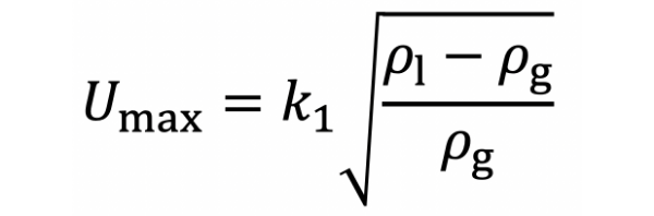
- Umax: max. allowable gas velocity [m/s]
- ρl: mist density[kg/m3]
- ρg: gas density [kg/m3]
- k1: Constant by Demi Star Style
If the speed of gas flow through mist eliminator is too high, collected mists may be scattered again.
On the other hand, if the speed is too low, mists may easily get on gas flow line and avoid contact with mist eliminator wire.
Therefore, we will design gas velocity ratio to be 70 - 80%. Gas velocity ratio of actual gas velocity to max. allowable gas velocity.
Collection Efficiency
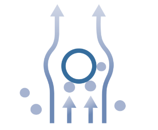
In Wire Mesh Mist Eliminator, mists( liquid drops ) are collected by contact with wires.
The mist comes into contact with the wire mainly due to the following effects.
- inertial collision
- interception
- diffusion by Brownian motion
The finest mist that can be fully captured in Wire Mesh Mist Eliminator is about 2μm.
Collection efficiency for one layer of wire mesh is calculated from efficiency of mist collision with one wire and multi-layered collection efficiency for entire Wire Mesh Mist Eliminator is calculated.
Mist collision efficiency with one wire is a function of Stokes number( dimensionless number, which indicates follow-up to flow of particles moving in fluid ).
Please refer to the catalog for specific calculation methods for collection efficiency.
Initial Pressure Drop
When gas pass through mist eliminator pad, pressure drop( pressure loss, differencial pressure ) is generated by resistance of Wire Mesh Mist Eliminator pad. Pressure drop by Wire Mesh Mist Eliminator is calculated as follows.
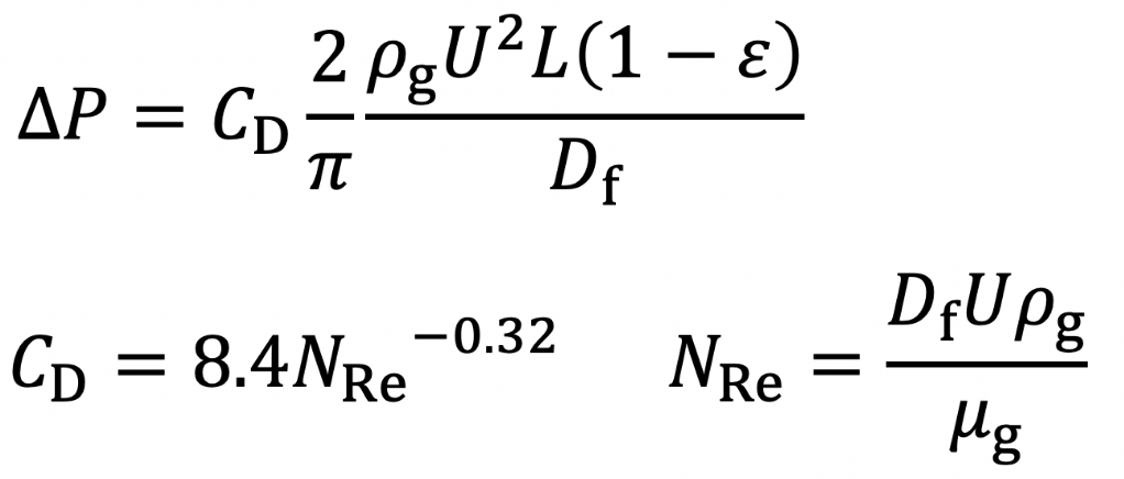
- ΔP: Pressure Drop [Pa]
- CD: drag coefficient [-]
- ρg: gas density[kg/m3]
- U: gas velocity [m/s]
- L: thickness of mist eliminator pad
- Df: wire diameter [m]
- ε: porosity[-]
- μg: gas viscosity [Pass]
Precautions for Use
Wire Mesh Mist Eliminator is usually made to the specifid size by cutting and laminating knitted mesh fabric, "C"-shaped wire chips are geneated.
We will remove chips as much as possible uring the production, but it is difficult to remove them completely.
As a production method that does not generate much chips. there is wound type. But it is still difficult to eliminate chips because the beginning and end of roll are cut.